XML Plan Forms
The Print menu option allows the user to select a plan form to be printed with a viewport.
A Plan Form contains the lines and text which form the border and explanatory text on a plan. The Plan Forms are
defined in a configuration file GeoSurvey_Config.xml which is an ASCII file which can be edited by the user.
See also .acs file Plan form - click here
A Sample plan form for an A4 sheet is shown here.
<Plan_Forms>
<form name="A4 Plan">
<window posn="0,20,260,200" />
<line colour="#000000" style=0 width=.5 posn="0,5,260,5" />
<line posn="260,5,260,200" />
<line posn="260,200,0,200" />
<line posn="0,200,0,5" />
<line posn="0,20,260,20" />
<line posn="80,5,80,20" />
<line posn="118,5,118,20" />
<line posn="220,5,220,20" />
<text font="Arial" size=4.5 colour="#0000ff" angle=0.0 bold=yes posn="5,14"
text="ACSP A4 Form Template" />
<text size=2.5 colour="#007700" bold=no posn="5,10"
text="Software for Surveyors" />
<text size=1.8 posn="5,6.5" text="http://www.users.bigpond.com/acscg" />
<text size=2.0 bold=yes posn="120,16" text="Mimaka Pty Limited" />
<text size=1.8 bold=no posn="120,13.5" text="57 Tryon Rd, Lindfield 2070" />
<text posn="120,11" text="PO Box 191, Killara 2071" />
<text posn="120,8.5" text="Ph: 0419.269.322" />
<text posn="120,6" text="mikef@mimaka.com.au" />
<text colour="#aa0000" posn="221,14" size=3 bold=yes text="Job: %vpname%" />
<text size=1.8 posn="221,10" text="Scale: 1:%scale%" />
<text posn="221,7" text="Date: %date%" />
<image file="mimlogo.bmp" posn="85,7.5" />
<symbol name="6" posn="50,100" size="5" angle="North" />
</form>
</Plan_Forms>
Each form has a name, in this case “A4 Plan”, and then has a number of commands:
<window> defines a window on the sheet in which the viewport will be printed
<line> draws a line on the sheet
<text> draws a text string on the sheet
<image> draws an image on the sheet
<symbol> draws an symbol on the sheet - see below for North Point Symbol.
Window
<window posn="0,20,260,200" />
The posn command gives two co-ords, the lower left and upper right co-ords in sheet mm of the viewport window.
Thus the lower left is 0,20 and the upper right is 260,200.
Line
<line colour="#000000" style=0 width=.5 posn="0,5,260,5" />
<line posn="260,5,260,200" />
The posn command gives the start and end co-ords for the line, 0,5 to 260,5.
The colour command defines the colour of the line as a Red-Green-Blue hexadecimal number, ‘RRGGBB’ where RR can
be 0-ff, the number specifies the intensity of the colour. Thus #FF0000 is a red line, #00FF00 is a green line,
#0000FF is a blue line, #000077 is a dark blue line, #000000 is a black line, #FFFFFF is a white line.
See here for more info on colours.
(https://www.w3schools.com/colors/colors_picker.asp)
The line style is the standard ACS line style as a number 0-n.
Width is the thickness of the line in mm.
When a colour, style or width is defined, it is automatically carried on to the following lines.
Text
<text font="Arial" size=4.5 colour="#0000ff" angle=0.0 bold=yes posn="5,14"
text="ACSP A4 Form Template" />
<text size=2.5 colour="#007700" bold=no posn="5,10"
text="Software for Surveyors" />
<text size=1.8 posn="5,6.5" text="http://www.users.bigpond.com/acscg" />
- The font is a Windows font to be used for the text.
- Size is the height of the text in mm.
- The colour command defines the colour of the line as a Red-Green-Blue hexadecimal number, ‘RRGGBB’, see the
colour explanation below for more details
- Angle is the cartesian angle, 0=normal left to right text, 90=vertically upwards.
- Bold is a yes/no attribute.
- Italic is a yes/no attribute.
- Underline is a yes/no attribute.
- Posn command gives the co-ordinates of the starting point for the text in mm on the sheet.
- Text command gives the text to be printed.
Note: When the font, size, colour, angle, bold, italic or underline are NOT defined,
they are automatically carried on from the previous text item.
Thus you only need to specify these values when they change.
Special text strings will be replaced with job parameters.
<text colour="#aa0000" posn="221,14" size=3 bold=yes text="Job: %vpname%" />
<text size=1.8 posn="221,10" text="Scale: 1:%scale%" />
<text posn="221,7" text="Date: %date%" />
- Thus %vpname% will be replaced with the viewport name, this should be the plan name.
- %scale% = Is the viewport scale.
- %date% = Is the current PC date (today).
- %username% = Is the Username taken from field on Job Parameters screen.
- %filename% = Is the current filename including path
- %jobfile% = The current filename excluding the path.
- %jobpath% = The file path(folder) to the current job.
- %datum/zone% = Is the job datum and zone
- %title1% = Top Title Line
- %title2% = Middle Title Line
- %title3% = Bottom Title Line
- %client% = Client name
- %jobref% = Job Reference
- %sheetno% = Sheet No
- %total_sheets% = Total sheets
- %revision% = Revision No
- %surveyor% = Surveyor
- %checked% = Checked
- %survdate% = Survey Date
- %vertical_datum% = Job Vertical Datum
- %proj_code% = Projection Code - from csv file column 16
- %proj_descr% = Projection Description - from csv file column 17
- %proj_source% = Projection Source/Authority - from csv file column 18
Image
<image file="mimlogo.jpg" posn="85,7.5" />
The file command indicates the file containing the bitmap image to be printed on the plan.
The posn command gives the x,y co-ords of the bottom left corner of the bitmap position.
Place the image file in the same folder as the config file.
The program will accept .bmp files or jpg files.
To edit or resize an image file you will need to use an Image Editor
Colour
<text size=4.5 colour="#ff0000" text=”Hello” />"
See also Colours.
Symbol - North Point Symbol
<symbol name="6" posn="50,100" size="5" angle="North" />
The symbol name must be one of the symbols available in the job symbol list.
Posn command gives the co-ordinates of the starting point for the text in mm on the sheet.
Size command gives the size of the symbol on the sheet.
Angle - This is the angle/bearing of the symbol in decimal degrees.
If you want to orient the symbol towards North, enter "North" and the
program will point it at North whatever viewport rotation is used.
Scale_bar
<scale_bar posn="10,26" width="50" txsize="3" />
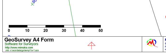
This picture shows examples of a 'symbol' North Point, an 'image' and a 'scale_bar'.
The POSN parameters are the x,y position of the start of the scale bar on the plan, in mm.
The 'width' is width of the scale bar in mm.
The 'txsize' is the height of the text in mm.
Advanced XML Plan Forms
You can define variables with values:
<define name="right_bdr" value="283" />
This defines a variable called "right_bdr" to have a value of "238" (millimetres).
When the variable is encountered further down in the Plan Form, the value will be substituted for the name.
This gives you an easy way to define a boundary value, and use it several times in the plan form.
You can define up to 30 different variables. You can also change the value of a variable at any time with another 'defin' command.
<Plan_Forms>
<form name="A3 Portrait">
<window posn="1.5,35.5,283.5,409" />
<define name="left_bdr" value="1" />
<define name="right_bdr" value="283" />
<define name="bottom_bdr" value="2.5" />
<define name="top_bdr" value="409" />
<!-- A3 PORTRAIT BORDER -->
<line colour="#000000" style=0 width=.25 />
<line posn="left_bdr, bottom_bdr, right_bdr, bottom_bdr" /> <!-- bottom border -->
<line posn="right_bdr,bottom_bdr, right_bdr,top_bdr" /> <!-- right border -->
<line posn="right_bdr,top_bdr, left_bdr,top_bdr" /> <!-- top border -->
<line posn="left_bdr,top_bdr, left_bdr,bottom_bdr" /> <!-- left border -->
<line posn="left_bdr,23.5, right_bdr,23.5" /> <!-- top line of title box -->
<line posn="17,bottom_bdr, 17,23.5" /> <!-- Left vertical line -->
<line posn="60,8.5, 60,23.5" /> <!-- Middle vertical line -->
<line posn="120,5.5,120,23.5" /> <!-- vertical left of logo -->
<line posn="170,bottom_bdr, 170,23.5" /> <!-- vertical right of logo -->
<line posn="240,bottom_bdr, 240,5.5" /> <!-- ORIG SIZE vertical line -->
<line posn="257,bottom_bdr, 257,5.5" /> <!-- SHEET vertical line -->
<line posn="17,5.5, right_bdr,5.5" /> <!-- FILE horiz line -->
<line posn="17,8.5, 120,8.5" /> <!-- Email horiz line -->
<line posn="17,11.5, 120,11.5" /> <!-- CHECKED horiz line -->
<line posn="17,14.5, 120,14.5" /> <!-- DRAWN BY horiz line -->
<line posn="17,17.5, 120,17.5" /> <!-- SURVEYOR horiz line -->
<line posn="17,20.5, 120,20.5" /> <!-- JOB horiz line -->
<line posn="170,8.5, right_bdr,8.5" /> <!-- CLIENT horiz line -->
....
</form>
</Plan_Forms>
Editing Plan Forms
A text editor is a progam/application that can be used to edit the contents of a text file.
Click here for more info.
Contents
Index